鈭?/div>
FUNCTION
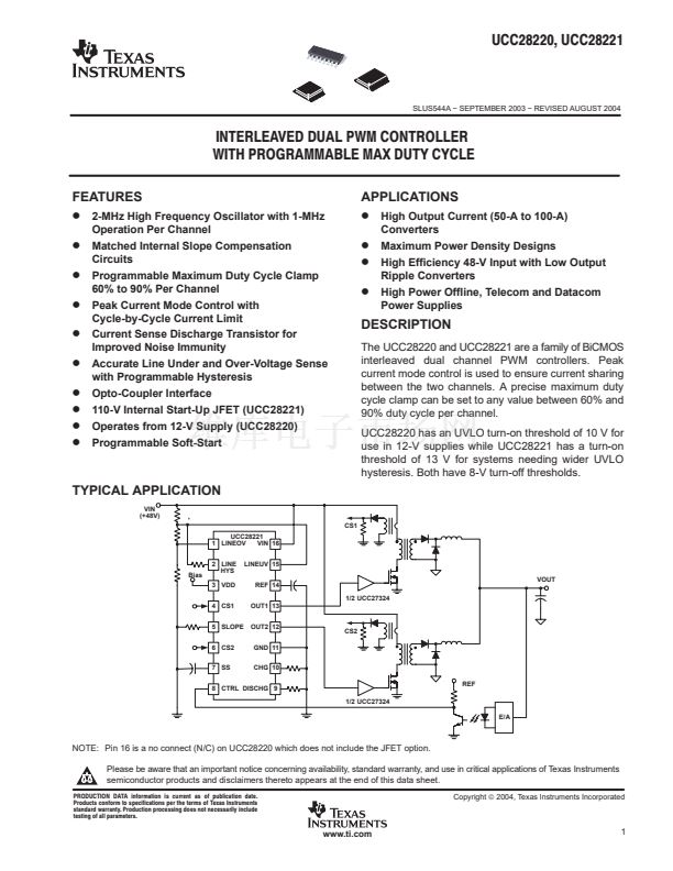
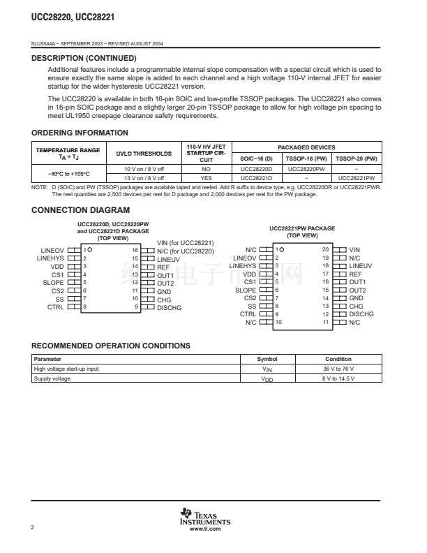
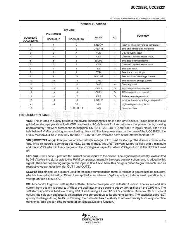
Input for line over voltage comparator
Sets line comparator hysteresis
Device supply input
Channel 1 current sense input
Sets slope compensation
Channel 2 current sense input
Soft-start input
Feedback control input
Sets oscillator discharge current
Sets oscillator charge current
Device ground
PWM output from channel 2
PWM output from channel 1
Reference voltage output
Input for line under voltage comparator
High voltage start-up input
No connection
PIN DESCRIPTIONS
VDD:
This is used to supply power to the device, monitoring this pin is a the UVLO circuit. This is used to insure
glitch-free startup operation. Until VDD reaches its UVLO threshold, it remains in a low power mode, drawing
approximately 150
碌A(chǔ)
of current and forcing pins, SS, CS1, CS2, OUT1, and OUT2 to logic 0 states. If the VDD
falls below 8 V after reaching turn-on, it will go back into this low power state. In the case of the UCC28221, the
UVLO threshold is 13 V. It is 10 V for the UCC28220. Both versions have a turn-off threshold of 8 V.
VIN (UCC28221 only):
This pin has an internal high voltage JFET used for startup. The drain is connected to
VIN, while its鈥?source is connected to VDD. During startup, this JFET delivers 12 mA typically with a minimum
of 4 mA to VDD, which in turn, charges up the VDD bypass capacitor. When VDD gets to 13 V, the JFET is turned
off.
CS1 and CS2:
These 2 pins are the current sense inputs to the device. The signals are internally level shifted
by 0.5 V before the signal gets to the PWM comparator. Internally the slope compensation ramp is added to this
signal. The linear operating range on this input is 0 to 1.5 V. Also, this pin gets pulled to ground each time its
respective output goes low. (ie: OUT1 and OUT2).
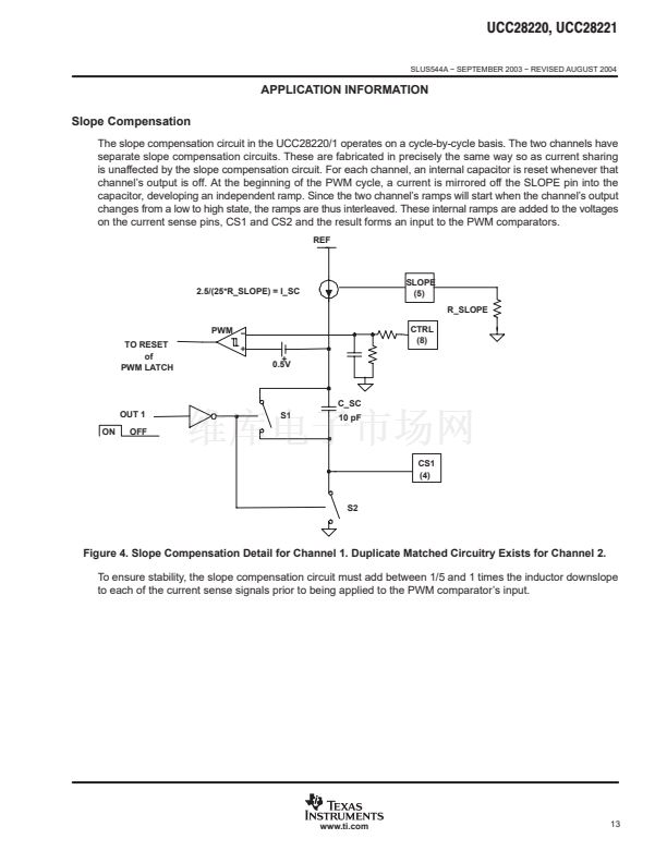
SLOPE:
This pin sets up a current used for the slope compensation ramp. A resistor to ground sets up a current,
which is internally divided by 25 and then applied to an internal 10-pF capacitor. Under normal operation th dc
voltage on this pin is 2.5 V..
SS:
A capacitor to ground sets up the soft-start time for the open loop soft-start function. The source and sink
current from this pin is equal to 3/7th of the oscillator charge current set by the resistor on the CHG pin. The
soft start capacitor is held low during UVLO and during a Line OV or UV condition. Once an OV or UV fault
occurs, the soft-start capacitor is discharged by a current equal to its charging current. The capacitor does NOT
quickly discharge during faults. In this way, the controller has the ability to recover quickly from very short line
transients. This pin can also be used as an Enable/Disable function.
www.ti.com
7


 1
1
 2
2
 3
3
 4
4
 5
5
 6
6
 7
7
 8
8
 9
9
 10
10
 11
11
 12
12
 13
13
 14
14
 15
15
 16
16
 17
17
 18
18
 19
19
 20
20
 21
21
 22
22
 23
23
 24
24
