UCC28220, UCC28221
SLUS544A 鈭?SEPTEMBER 2003 鈭?REVISED AUGUST 2004
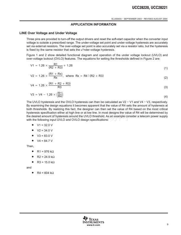
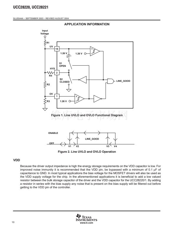
APPLICATION INFORMATION
Slope Compensation
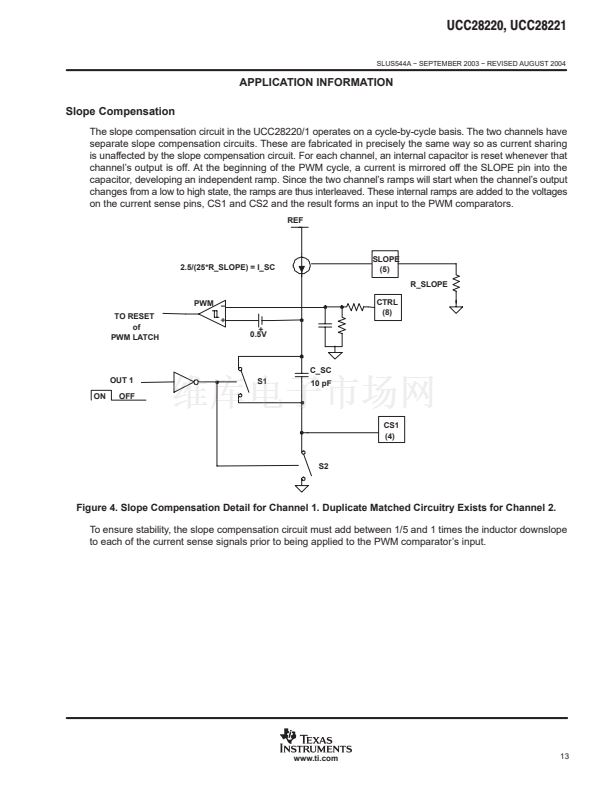
The slope compensation circuit in the UCC28220/1 operates on a cycle-by-cycle basis. The two channels have
separate slope compensation circuits. These are fabricated in precisely the same way so as current sharing
is unaffected by the slope compensation circuit. For each channel, an internal capacitor is reset whenever that
channel鈥檚 output is off. At the beginning of the PWM cycle, a current is mirrored off the SLOPE pin into the
capacitor, developing an independent ramp. Since the two channel鈥檚 ramps will start when the channel鈥檚 output
changes from a low to high state, the ramps are thus interleaved. These internal ramps are added to the voltages
on the current sense pins, CS1 and CS2 and the result forms an input to the PWM comparators.
REF
2.5/(25*R_SLOPE) = I_SC
SLOPE
(5)
R_SLOPE
PWM 鈭?/div>
TO RESET
of
PWM LATCH
+
0.5V
+
CTRL
(8)
C_SC
OUT 1
ON
OFF
S1
10 pF
CS1
(4)
S2
Figure 4. Slope Compensation Detail for Channel 1. Duplicate Matched Circuitry Exists for Channel 2.
To ensure stability, the slope compensation circuit must add between 1/5 and 1 times the inductor downslope
to each of the current sense signals prior to being applied to the PWM comparator鈥檚 input.
www.ti.com
13


 1
1
 2
2
 3
3
 4
4
 5
5
 6
6
 7
7
 8
8
 9
9
 10
10
 11
11
 12
12
 13
13
 14
14
 15
15
 16
16
 17
17
 18
18
 19
19
 20
20
 21
21
 22
22
 23
23
 24
24
