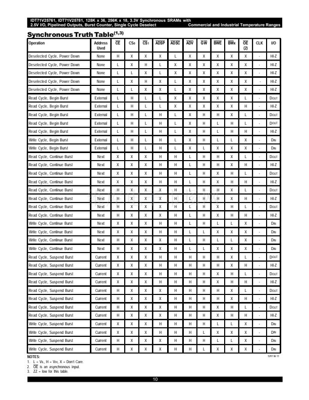
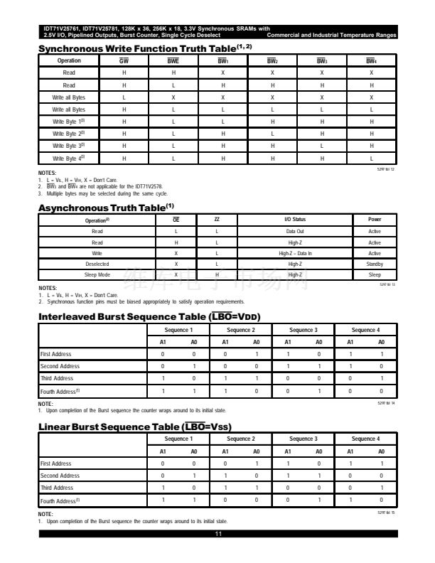
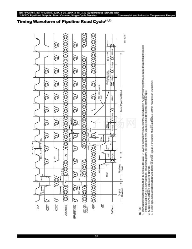
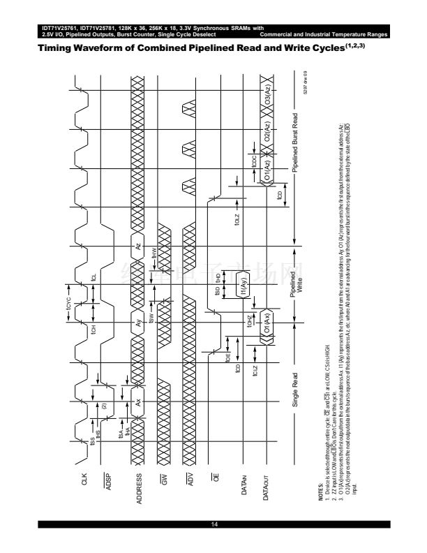
IDT71V25761, IDT71V25781, 128K x 36, 256K x 18, 3.3V Synchronous SRAMs with
2.5V I/O, Pipelined Outputs, Burst Counter, Single Cycle Deselect
Commercial and Industrial Temperature Ranges
Pin Configuration 聳 128K x 36
A
6
A
7
CE
CS
0
BW
4
BW
3
BW
2
BW
1
CS
1
V
DD
V
SS
CLK
GW
BWE
OE
ADSC
ADSP
ADV
A
8
A
9
100 99 98 97 96 95 94 93 92 91 90 89 88 87 86 85 84 83 82 81
I/O
P3
I/O
16
I/O
17
V
DDQ
V
SS
I/O
18
I/O
19
I/O
20
I/O
21
V
SS
V
DDQ
I/O
22
I/O
23
V
DD
/NC
(1)
V
DD
NC
V
SS
I/O
24
I/O
25
V
DDQ
V
SS
I/O
26
I/O
27
I/O
28
I/O
29
V
SS
V
DDQ
I/O
30
I/O
31
I/O
P4
1
2
3
4
5
6
7
8
9
10
11
12
13
14
15
16
17
18
19
20
21
22
23
24
25
26
27
28
29
30
31 32 33 34 35 36 37 38 39 40 41 42 43 44 45 46 47 48 49 50
80
79
78
77
76
75
74
73
72
71
70
69
68
67
66
65
64
63
62
61
60
59
58
57
56
55
54
53
52
51
I/O
P2
I/O
15
I/O
14
V
DDQ
V
SS
I/O
13
I/O
12
I/O
11
I/O
10
V
SS
V
DDQ
I/O
9
I/O
8
V
SS
NC
V
DD
ZZ
(3)
I/O
7
I/O
6
V
DDQ
V
SS
I/O
5
I/O
4
I/O
3
I/O
2
V
SS
V
DDQ
I/O
1
I/O
0
I/O
P1
5297 drw 02
,
LBO
A
5
A
4
A
3
A
2
A
1
A
0
100 TQFP
Top View
NOTES:
1. Pin 14 can either be directly connected to V
DD
, or connected to an input voltage
鈮?/div>
V
IH
, or left unconnected.
2. Pins 38 and 39 can be either NC or connected to V
SS.
3. Pin 64 can be left unconnected and the device will always remain in active mode.
NC
(2)
NC
(2)
V
SS
V
DD
NC
NC
A
10
A
11
A
12
A
13
A
14
A
15
A
16
6.42
5


 1
1
 2
2
 3
3
 4
4
 5
5
 6
6
 7
7
 8
8
 9
9
 10
10
 11
11
 12
12
 13
13
 14
14
 15
15
 16
16
 17
17
 18
18
 19
19
 20
20
 21
21
 22
22
 23
23
