ST7538
Table 5. Vout vs. R1 & R2 resistors value
Vout (Vrms)
0.150
0.250
0.350
0.500
0.625
0.750
0.875
1.000
1.250
1.500
Vout (dB碌V)
103.5
108.0
110.9
114.0
115.9
117.5
118.8
120.0
121.9
123.5
(R1+R2)/R2
1.1
1.9
2.7
3.7
4.7
5.8
6.6
7.6
9.5
10.8
R2 (K鈩?
7.5
5.1
3.6
3.3
3.3
2.7
2.0
1.6
1.6
1.6
R1 (K鈩?
1.0
3.9
5.6
8.2
11.0
12.0
11.0
10.0
13.0
15.0
Notes: The rate of R2 takes in account the input resistance on the SENSE pin (36 K鈩?.
5.6nF capacitor effect has been neglected.
Figure 14. Typical Output Current vs. Rcl
Irms
(mA)
325
300
275
250
225
200
175
150
125
100
2
2.5
3
3.5
4
4.5
5
D01IN1311
Rcl(K鈩?
s
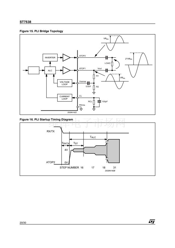
Integrated Power Line Interface (PLI)
The Power Line Interface (PLI) is a double CMOS AB Class Power Amplifier with the two outputs
(ATOP1 and ATOP2) in opposition of phase.
Two are the possible configuration:
- Single Ended Output (ATOP1).
- Bridge Connection
The Bridge connection guarantee a Differential Output Voltage to the load with twice the swing of each
individual Output. This topology virtually eliminates the even harmonics generation.
The PLI requires, to ensure a proper operation, a regulated and well filtered Supply Voltage. PAVcc
Voltage must fulfil the following formula to work without clipping phenomena:
PAVcc
鈮?/div>
VATOP
(
AC
)
+
7.5V
-----------------------------------
-
2
To allow the driving of an external Power Line Interface, the output of the ALC is available even on ATO
pin. ATO output has a current capability much lower than ATOP1 and ATOP2.
19/30


 1
1
 2
2
 3
3
 4
4
 5
5
 6
6
 7
7
 8
8
 9
9
 10
10
 11
11
 12
12
 13
13
 14
14
 15
15
 16
16
 17
17
 18
18
 19
19
 20
20
 21
21
 22
22
 23
23
 24
24
 25
25
 26
26
 27
27
 28
28
 29
29
 30
30
