30碌s.
Figure 3a.
Figure 3c. AutoShutdown Plus Logic
30碌s.
* POWERDOWN IS ONLY AN INTERNAL SIGNAL.
THE TRANSMITTERS AND THE POWER SUPPLIES.
Figure 3b.
Figure 3d. Power-Down Logic
Table 2.
or operating system.
receiver voltage levels.
states. Figure 3 and Tables 1 and 2 sum-
marize the operating modes of the MAX3224E鈥?/div>
MAX3227E/MAX3244E/MAX3245E. FORCEON and
FORCEOFF
override AutoShutdown Plus circuitry.
When neither control is asserted, the IC selects
between these states automatically based on the last
receiver or transmitter input edge received.
When shut down, the device鈥檚 charge pumps turn off,
V+ is pulled to V
CC
, V- is pulled to ground, the transmit-
ter outputs are high impedance, and READY
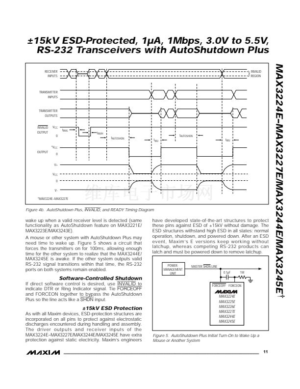
(MAX3224E鈥?MAX3227E) is driven low. The time
required to exit shutdown is typically 100碌s (Figure 8).
By connecting FORCEON to
INVALID,
the MAX3224E鈥?/div>
MAX3227E/MAX3244E/MAX3245E shut down when no
valid receiver level and no receiver or transmitter edge is
detected for 30sec, and wake up when a valid receiver
level or receiver or transmitter edge is detected.
By connecting FORCEON and
FORCEOFF
to
INVALID,
the MAX3224E鈥揗AX3227E/MAX3244E/MAX3245E shut
down when no valid receiver level is detected and
INVALID HIGH
+2.7V
RECEIVER INPUT LEVELS
INDETERMINATE
+0.3V
0
-0.3V
INDETERMINATE
-2.7V
INVALID HIGH
INVALID LOW
Figure 4a. Receiver Positive/Negative Thresholds for
INVALID
10
______________________________________________________________________________________


 1
1
 2
2
 3
3
 4
4
 5
5
 6
6
 7
7
 8
8
 9
9
 10
10
 11
11
 12
12
 13
13
 14
14
 15
15
 16
16
 17
17
 18
18
 19
19
 20
20
