4 Mbit Multi-Purpose Flash
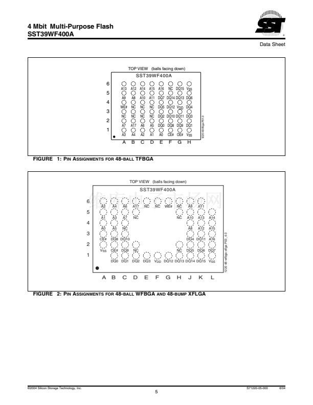
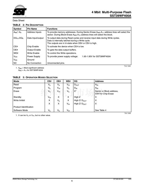
SST39WF400A
Data Sheet
AC CHARACTERISTICS
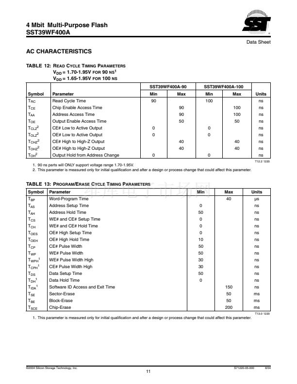
TABLE 12: R
EAD
C
YCLE
T
IMING
P
ARAMETERS
V
DD
= 1.70-1.95V
FOR
90
NS1
V
DD
= 1.65-1.95V
FOR
100
NS
SST39WF400A-90
Symbol
T
RC
T
CE
T
AA
T
OE
T
CLZ2
T
OLZ2
T
CHZ2
T
OHZ2
T
OH2
Parameter
Read Cycle Time
Chip Enable Access Time
Address Access Time
Output Enable Access Time
CE# Low to Active Output
OE# Low to Active Output
CE# High to High-Z Output
OE# High to High-Z Output
Output Hold from Address Change
0
0
0
40
40
0
Min
90
90
90
50
0
0
40
40
Max
SST39WF400A-100
Min
100
100
100
50
Max
Units
ns
ns
ns
ns
ns
ns
ns
ns
ns
T12.2 1220
1. 90 ns parts will ONLY support voltage range 1.70-1.95V.
2. This parameter is measured only for initial qualification and after a design or process change that could affect this parameter.
TABLE 13: P
ROGRAM
/E
RASE
C
YCLE
T
IMING
P
ARAMETERS
Symbol
T
BP
T
AS
T
AH
T
CS
T
CH
T
OES
T
OEH
T
CP
T
WP
T
WPH1
T
CPH1
T
DS
T
DH1
T
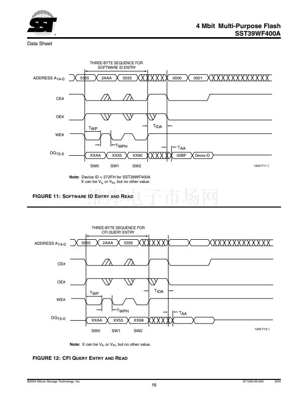
IDA1
T
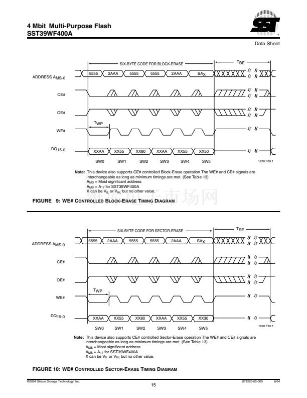
SE
T
BE
T
SCE
Parameter
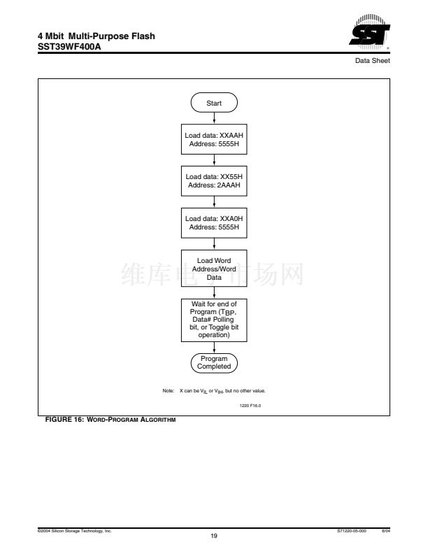
Word-Program Time
Address Setup Time
Address Hold Time
WE# and CE# Setup Time
WE# and CE# Hold Time
OE# High Setup Time
OE# High Hold Time
CE# Pulse Width
WE# Pulse Width
WE# Pulse Width High
CE# Pulse Width High
Data Setup Time
Data Hold Time
Software ID Access and Exit Time
Sector-Erase
Block-Erase
Chip-Erase
0
50
0
0
0
10
50
50
30
30
50
0
150
50
50
200
Min
Max
40
Units
碌s
ns
ns
ns
ns
ns
ns
ns
ns
ns
ns
ns
ns
ns
ms
ms
ms
T13.0 1220
1. This parameter is measured only for initial qualification and after a design or process change that could affect this parameter.
漏2004 Silicon Storage Technology, Inc.
S71220-05-000
6/04
11


 1
1
 2
2
 3
3
 4
4
 5
5
 6
6
 7
7
 8
8
 9
9
 10
10
 11
11
 12
12
 13
13
 14
14
 15
15
 16
16
 17
17
 18
18
 19
19
 20
20
 21
21
 22
22
 23
23
 24
24
 25
25
 26
26
