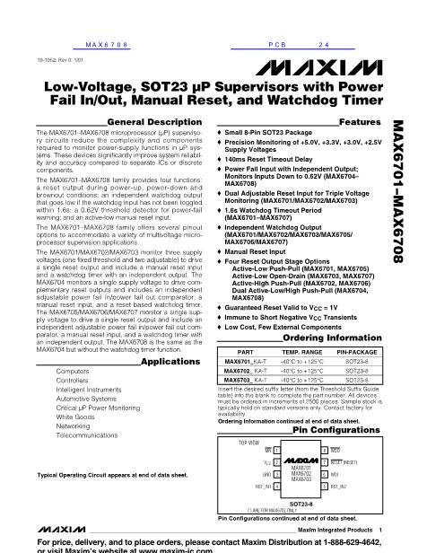
Low-Voltage, SOT23 碌P Supervisors with Power-
Fail In/Out, Manual Reset, and Watchdog Timer
MAX6701鈥?8/MAX6701A鈥?3A/05A鈥?7A
ABSOLUTE MAXIMUM RATINGS
V
CC
........................................................................-0.3V to +6.0V
Open-Drain
RESET, WDO, PFO
...........................-0.3V to +6.0V
Push-Pull RESET,
RESET, WDO, PFO
........-0.3V to (V
CC
+ 0.3V)
MR,
WDI, PFI, RST_IN1, RST_IN2 ..............-0.3V to (V
CC
+ 0.3V)
Input Current (V
CC
) .............................................................20mA
Output Current (RESET, RESET,
PFO, WDO)
.....................20mA
Continuous Power Dissipation (T
A
= +70擄C)
8-Pin SOT23 (derate 8.9mW/擄C above +70擄C)............714mW
Operating Temperature Range .........................-40擄C to +125擄C
Junction Temperature ......................................................+150擄C
Storage Temperature Range .............................-65擄C to +150擄C
Lead Temperature (soldering, 10s) .................................+300擄C
Stresses beyond those listed under 鈥淎bsolute Maximum Ratings鈥?may cause permanent damage to the device. These are stress ratings only, and functional
operation of the device at these or any other conditions beyond those indicated in the operational sections of the specifications is not implied. Exposure to
absolute maximum rating conditions for extended periods may affect device reliability.
ELECTRICAL CHARACTERISTICS
(V
CC
= +4.25V to +5.5V for L/M versions, V
CC
= +2.55V to +3.6V for the T/S/R versions, V
CC
= +2.1V to +2.75V for the Z/Y versions.
T
A
= -40擄C to +125擄C, unless otherwise specified. Typical values are at T
A
= +25擄C.) (Note 1)
PARAMETER
Operating Voltage Range
Supply Current
MR
Unconnected
SYMBOL
V
CC
CONDITIONS
T
A
= 0擄C to +125擄C
T
A
= -40擄C to +125擄C
V
CC
< 5.5V, no load
I
CC
V
CC
< 3.6V, no load
V
CC
< 3.6V, no load (MAX6708 only)
MAX670_L/MAX670_AL
MAX670_M/MAX670_AM
MAX670_T/MAX670_AT
V
CC
Reset Threshold
(V
CC
falling)
V
TH
MAX670_S/MAX670_AS
MAX670_R/MAX670_AR
MAX670_Z/MAX670_AZ
MAX670_Y/MAX670_AY
Reset Threshold
Temperature Coefficient
V
CC
to Reset Output Delay
Reset Timeout Period
V
CC
Falling to
WDO
Delay
PFI, RST_IN1, RST_IN2
Threshold
PFI Hysteresis
t
RP
鈭哣
TH
V
CC
falling at 10mV/碌s
T
A
= -40擄C to +85擄C
T
A
= -40擄C to +125擄C
MAX6701(A)/MAX6702(A)/MAX6703(A)/MAX6705(A)/
MAX6706(A)/MAX6707(A)
V
CC
= 1.8V to 5.5V
T
A
= -40擄C to +85擄C
T
A
= -40擄C to +125擄C
602
593
6
140
120
5
618
634
642
T
A
= -40擄C to +85擄C
T
A
= -40擄C to +125擄C
T
A
= -40擄C to +85擄C
T
A
= -40擄C to +125擄C
T
A
= -40擄C to +85擄C
T
A
= -40擄C to +125擄C
T
A
= -40擄C to +85擄C
T
A
= -40擄C to +125擄C
T
A
= -40擄C to +85擄C
T
A
= -40擄C to +125擄C
T
A
= -40擄C to +85擄C
T
A
= -40擄C to +125擄C
T
A
= -40擄C to +85擄C
T
A
= -40擄C to +125擄C
4.50
4.47
4.25
4.22
3.00
2.97
2.85
2.83
2.55
2.53
2.25
2.24
2.12
2.11
60
12
200
280
300
2.19
2.32
2.63
2.93
3.08
4.38
MIN
1.0
1.2
12
9
6
4.63
TYP
MAX
5.5
5.5
25
20
20
4.75
4.78
4.50
4.53
3.15
3.17
3.00
3.02
2.70
2.72
2.38
2.40
2.25
2.27
ppm/擄C
碌s
ms
碌s
mV
mV
V
碌A(chǔ)
UNITS
V
2
_______________________________________________________________________________________


 1
1
 2
2
 3
3
 4
4
 5
5
 6
6
 7
7
 8
8
 9
9
 10
10
 11
11
 12
12
