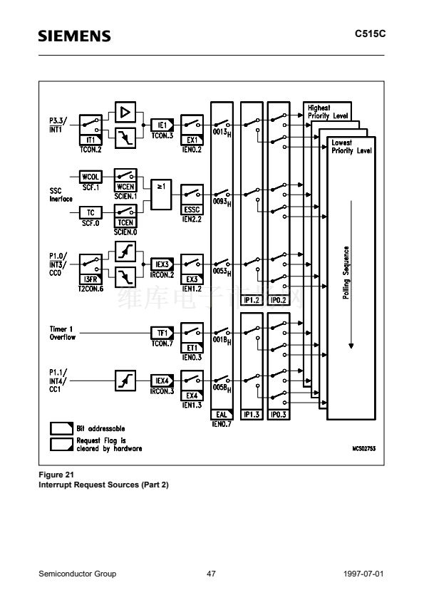
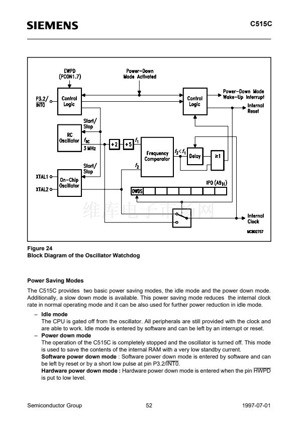
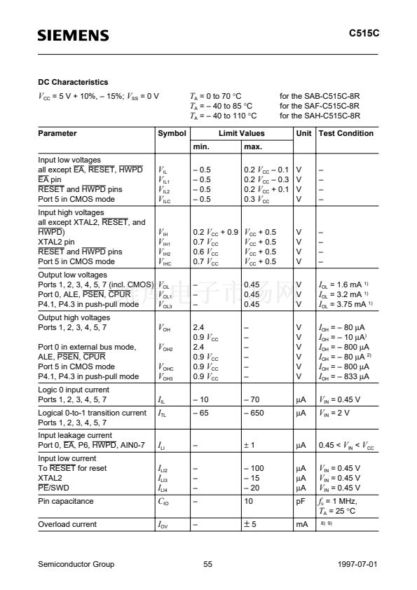
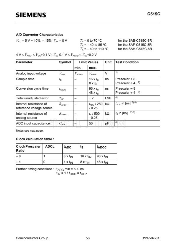
C515C
Timer / Counter 0 and 1
Timer/Counter 0 and 1 can be used in four operating modes as listed in
table 6
:
Table 6
Timer/Counter 0 and 1 Operating Modes
Mode
0
1
2
3
Description
8-bit timer/counter with a
divide-by-32 prescaler
16-bit timer/counter
8-bit timer/counter with
8-bit autoreload
Timer/counter 0 used as one
8-bit timer/counter and one
8-bit timer / Timer 1 stops
TMOD
M1
0
0
1
1
M0
0
1
0
1
Timer/Counter Input Clock
internal
external (max)
f
OSC
/6 x 32
f
OSC
/12 x 32
f
OSC
/6
f
OSC
/12
In the 鈥渢imer鈥?function (C/T = 鈥?鈥? the register is incremented every machine cycle. Therefore the
count rate is
f
OSC
/6.
In the 鈥渃ounter鈥?function the register is incremented in response to a 1-to-0 transition at its
corresponding external input pin (P3.4/T0, P3.5/T1). Since it takes two machine cycles to detect a
falling edge the max. count rate is
f
OSC
/12. External inputs INT0 and INT1 (P3.2, P3.3) can be
programmed to function as a gate to facilitate pulse width measurements.
Figure 11
illustrates the
input clock logic
OSC
梅6
C/T = 0
f
OSC
/6
Timer 0/1
Input Clock
C/T = 1
P3.4/T0
P3.5/T1
TR0
TR1
_
<1
Control
&
Gate
(TMOD)
P3.2/INT0
P3.3/INT1
=1
MCS03117
Figure 11
Timer/Counter 0 and 1 Input Clock Logic
Semiconductor Group
33
1997-07-01


 1
1
 2
2
 3
3
 4
4
 5
5
 6
6
 7
7
 8
8
 9
9
 10
10
 11
11
 12
12
 13
13
 14
14
 15
15
 16
16
 17
17
 18
18
 19
19
 20
20
 21
21
 22
22
 23
23
 24
24
 25
25
 26
26
 27
27
 28
28
 29
29
 30
30
 31
31
 32
32
 33
33
 34
34
 35
35
 36
36
 37
37
 38
38
 39
39
 40
40
 41
41
 42
42
 43
43
 44
44
 45
45
 46
46
 47
47
 48
48
 49
49
 50
50
 51
51
 52
52
 53
53
 54
54
 55
55
 56
56
 57
57
 58
58
 59
59
 60
60
 61
61
 62
62
 63
63
 64
64
 65
65
 66
66
 67
67
 68
68
 69
69
