廬
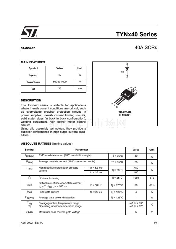
TYNx40 Series
40A SCRs
STANDARD
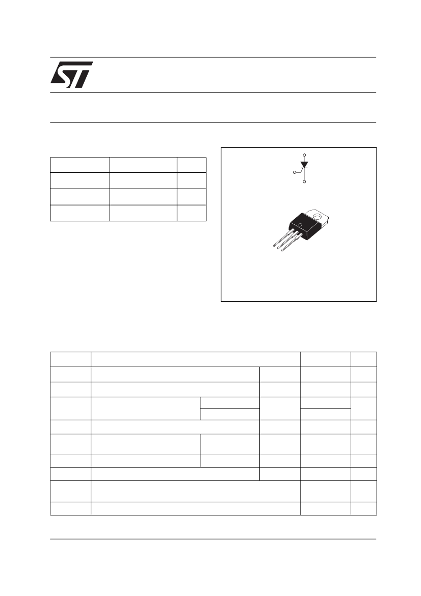
MAIN FEATURES:
Symbol
I
T(RMS)
V
DRM
/V
RRM
I
GT
Value
40
600 to 1000
35
Unit
G
A
A
K
V
mA
A
DESCRIPTION
The TYNx40 series is suitable for applications
where in-rush current conditions are critical, such
as overvoltage crowbar protection circuits in
power supplies, in-rush current limiting circuits,
solid state relays (in back to back configuration),
welding equipment, high power motor control
circuits.
Using clip assembly technology, they provide a
superior performance in high surge current capa-
bilites.
ABSOLUTE RATINGS
(limiting values)
Symbol
I
T(RMS)
IT
(AV)
I
TSM
Parameter
RMS on-state current (180擄 conduction angle)
Average on-state current (180擄 conduction angle)
Non repetitive surge peak on-state
current
I
虜
t Value for fusing
Critical rate of rise of on-state current
I
G
= 2 x I
GT
, tr
鈮?/div>
100 ns
Peak gate current
Average gate power dissipation
Storage junction temperature range
Operating junction temperature range
Maximum peak reverse gate voltage
F = 60 Hz
tp = 20 碌s
tp = 8.3 ms
tp = 10 ms
Tj = 25擄C
Tj = 125擄C
Tj = 125擄C
Tj = 125擄C
Tc = 95擄C
Tc = 95擄C
Tj = 25擄C
Value
40
25
480
460
1060
50
4
1
- 40 to + 150
- 40 to + 125
5
A
2
S
A/碌s
A
W
擄C
V
Unit
A
A
A
K
A
G
TO-220AB
(TYNx40)
I
虜
t
dI/dt
I
GM
P
G(AV)
T
stg
Tj
V
RGM
April 2002 - Ed: 4A
1/4


 1
1
 2
2
 3
3
 4
4
